Application Research of Pipeline Filter Mode in Digital Image Processing
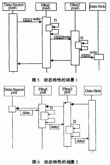
Pattern is the crystallization of the wisdom of software development practice, which in turn serves as a guide for software development. Depending on the stage of software development and the granularity of development, patterns can be divided into: architectural patterns, design patterns, and idioms. The pipeline and filter patterns in this article are one of the architectural patterns. 1 The main features are: (1) providing a structure for systems that process data; In the context of processing data streams, a system is created that must process or transform the input data stream. Such a system needs to meet the following mandatory conditions: the processing of data can be easily divided into several processing steps; the order of operations is exactly the same; the order of the data is exactly the same; the parallelism is handled; the upgrade of the system can be implemented by replacing/increasing the an/reorganization processing steps. Sometimes, even the user completes the operation; different processing steps do not share information; there are different input data sources; the load requirements are as balanced as possible. The following four types can be further subdivided in the system: (1) The system task is divided into several sequential processing steps, which are connected by a data stream, and each step is called a filter. (2) The input of the system is provided by a data source such as a text file or other. (3) The output of the system flows to the data sink. (4) Pipeline connection data source, filter and data sink, which is responsible for the data flow between adjacent steps. 3.1 filter structure The filter is the processing unit of the pipeline, responsible for enriching, refining or converting its input data, as shown in Figure 1. It works in three ways: the subsequent pipeline unit pulls the data out of the filter (passive filter); the front pipeline unit presses the new input data into the filter (passive filter); the filter loops The way to work, pull the input data from the pipeline and press its output data into the pipeline (active filter). The pipe represents the connection between the filters; the connection between the data source and the first filter; and the connection between the last filter and the data sink. If the pipeline connects two active filters, the pipeline needs to be buffered and synchronized, as shown in Figure 2. If the two active components are controlled by a filter in the pipeline, the pipeline can be called directly to implement. However, direct calls will make the reorganization of the filter more difficult. 3.4 Data Meeting Point Data sinks collect results from the pipeline end, as shown in Figure 4. There are two ways to work: the active data sink pulls the results of the previous processing phase; the passive data sink allows the previous filter to push or write the results in and out. The pipeline defines the flow direction of the data stream, but its control flow can be varied in many ways depending on the situation. Specific to determining the control flow, it can be determined according to which active components are in the actual system. The following are four scenarios of dynamic features (where n and f2 are calculation functions). Scenario 1: The pipeline is advanced, its activity starts from the data source, and each filter is a passive filter. As shown in Figure 5: 5.1 Divide system tasks into a series of processing stages (1) Each stage must rely solely on the output of the previous stage. (2) Need to pay attention to the method when replacing the processing steps: replacement when redesigning; replacement at runtime; replacement after installation. 5.2 define the data format transmitted along each pipe (1) Defining a uniform format for maximum flexibility, but may bring efficiency problems. 5.3 Decide how to implement each pipe connection (1) Determine if each filter is passive or active. 5.4 design and implementation of filters (1) Based on the tasks that the filter needs to accomplish, the adjacent pipes are used to design the filter. 5.5 design error handling (1) Error handling is difficult to do and is often ignored. 5.6 Consider the dynamic reorganization of pipelines (1) When it is necessary to reorganize the filter, first consider when it is possible to perform dynamic reorganization? The color bitmap input is a 24-bit true color map captured by video. In order to facilitate the processing of the image, the color map is grayscaled to form an 8-bit grayscale image. This can use the active filter to call the LoadBitMap() function to get the grayscale data stream. The gray level can be calculated by the current standard average value g = 0.3R + 0.59G + 0.1lB. (g: indicates the value after graying, R, G, B indicates red, green and blue ternary) Because the obtained image generally has some defects, such as insufficient light during imaging, the whole picture is dark, or the illumination is too strong when imaging, so that the whole picture is bright, resulting in low contrast of the image, which requires grayscale. Stretching. Grayscale stretching can be designed as an active filter to call the grayscale function ColorTransGray() as its own data input. Edge extraction can also use the active filter, call the gray stretch function GrayStreteh () as its own data input. The algorithm can be used by one of RoberDIB, SobelDIB, and Prewitt to generate an edge amplitude image, and the Hough transform to extract the line algorithm further complements the generated edge amplitude image. Template matching can be designed as a Pull and Push filter. On the one hand, it outputs the output of the edge extraction function as its own data stream, by calling the edge extraction function. On the other hand, the result of the template matching calculation is compressed by the pipeline. Verify and output the image object to read the data in the pipeline, call the CoutImage() function to output the character segmentation object. 7.1 Pipe and filter modes have many advantages A new processing pipeline can be created by reorganization and reuse of components. For example, in the example, the license plate location system is a processing pipeline without data sinks, which is added to the character segmentation recognition processing pipeline, plus the previous The acquisition of images forms a new processing pipeline for a car license plate recognition system. This means that the reorganization and reuse of pipes and filters adds flexibility to software development. Processing data streams does not necessarily require a middle file, which is another advantage of pipes and filters. In a system that puts intermediate results in a file, the scheduling strategy for the file directory is not easy. Moreover, the processing steps have to be re-established each time the system is run, which is error-prone. 7.2 Pipeline and filter mode also has its own shortcomings First, the unconnected processing steps do not share information. If the model has a large amount of shared global data, the system built with this model is not only inflexible but also expensive. Second, the use of a single data format for the input and output of all filters increases the overhead of data conversion. Third, error recovery and error handling strategies are difficult to achieve. This article only discusses the pipeline and filter modes, it is just one of many modes. The pattern covers all aspects of software development, depending on the application, different modes should be chosen, or multiple modes coexist at the same time. For example, the distributed system is developed by proxy mode, micro-core mode, pipeline and filter mode, and the interactive system is developed by M-A-V mode and P-A-V mode, and developed by image mode and micro-core mode. Adaptive systems, and so on, form the pattern system_1 J. Especially in the process of software development, we should use our experience and wisdom to develop mining models, organizational models and utilization models to play a guiding role in software development.
(2) Each processing step is encapsulated in a filter component, each filter can be modified separately, and its function is single;
(3) Data is transmitted through the pipeline between adjacent filters;
(4) Recombination filters can establish related system families;
(5) The filter is a stand-alone component:
1 Each filter is affected by any other filter operation except the input and output. That is, no state information is shared between the filters on the design;
2 A filter is "ignorant" to the upstream and downstream connected filters it processes; independence is also manifested in its design and use does not impose restrictions on any filters it connects to, the only concern is its input data, Then processing is performed, and finally the data output is generated. The basic feature of this mode application is that the system task is divided into several connected processing steps, the output of one step is the input of one step, and the processing and control of data are concurrently performed. An example of a typical pipeline filter architecture is a program written in Unix sheu. Unix provides both a symbol to connect components (a Unix process) and a process runtime mechanism to implement the pipeline. Another famous example is the traditional compiler. Traditional compilers have long been considered a pipeline system in which the output of one phase (including lexical analysis, parsing, semantic analysis, and code generation) is the input to another phase.
2 questions
3 four data structures used by the system 
3.2 Pipe structure 
The data source represents the input of the system, which provides a series of values ​​of the same structure or type, as shown in Figure 3. The data source of the pipeline can actively push the data value to the first processing stage, or passively provide data when the first filter is pulled out. 
4 Dynamics of the pipeline and filter modes 
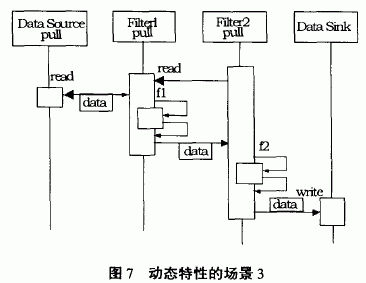
Scenario 2: Pull out the pipeline, its activity starts from the data sink, and each filter is an active filter. As shown in Figure 6.
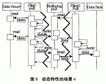
Scenario 3: Push the pull line and its activity starts with the second filter. As shown in Figure 7: 
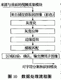
Scenario 4: A typical pipeline filter system in which all filters actively pull, calculate, and push data. In this case, each filter runs with its own control thread, and the filters are synchronized using pipes. As shown in Figure 8: 
5 implementation plan
(2) It must be defined how to identify the end of the input: 0 value, a value of 1 and so on.
(3) Other semantic control flags may be needed: such as the end of the data frame, the data exception flag, and so on.
(2) Define whether the data of each filter is initiated by pressing the data or pulling the data.
(3) Define how data is passed: by direct invocation; buffering and synchronizing through separate pipe mechanisms; at the same time, using the same pipe mechanism makes filter reorganization easier.
(2) Consider the need to copy data between address spaces.
(3) Consider the pipe buffer size.
(4) Consider reusing filters that control their behavior in a specific way: from which pipe to read data and to which pipe to send data?
(2) If a filter detects an error in its input data: it can ignore the input until some clear delimiter appears; stop processing, reset the state, wait for a particular start symbol to appear.
(3) It is difficult to give a general strategy for handling errors.
(2) How to redirect the input and output of the filter?
(3) Who starts it? Is there a control symbol added to the input data stream?
6 An application example of pipes and filters
If you want to develop such software: car license plate recognition system [citation. The system can generally be divided into vehicle image acquisition, vehicle license plate sub-image positioning and segmentation, and character recognition. The process is shown in Figure 9: 
Since the system task is divided into several sequential processing steps, these steps are connected by data flow, and the output of the previous step is the input of the next step, as shown in FIG. Thus the entire system can be applied to apply pipeline and filter modes. Not only the entire system, but also every step. The key steps of the system are the first and second block diagrams of the above figure, and the development quality of the second block diagram directly affects the third block diagram. The pipeline and filter modes are now used to develop the positioning of the license plate image of the second block diagram. The corresponding object modeling diagram can be designed as Figure 1: 

The scene in which the object modeling diagram appears is as follows [ ]:
7 effects
8 Conclusion